last updated 25 Sep 2003The "naughty stuff" page II...
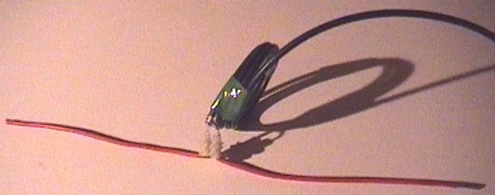
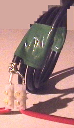
Some experimentsThanks to "details withheld" for the following..."I made a dipole using two parts of a 3 amp connector block, two bits of red-insulated chunky wire that started off at 18cm long each, and an old computer network coax cable that already had BNC connectors on each end. Cutting the cable in half I had one end to put the dipole on, and the other end to play with couplers. A VSWR/Power meter conveniently hooked up to the BNC connectors. The dipole ended up tuned to about 440MHz, with a VSWR reading of 1.4, although it must be said that the meter was only rated up to the 2m band but I still believe it gives some useful indication up here even if it's not spot on. The reading down at 433MHz was 1.7, perfectly adequate for our purposes, and the reading would be similar on 446MHz I'm sure, being almost just as far from 440. The overall length of the dipole itself was 35cm. Here are some pictures. The cable was coiled around a few times in an attempt to function as a 'choke' balun, to force the correct state of affairs with a balanced antenna and unbalanced feeder by preventing RF currents flowing back down the outside of the coax screen. By the way, green tape was the first reel I had to hand, so there.
|
|
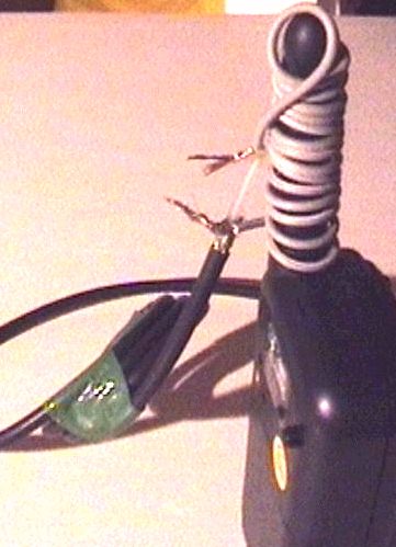
"The dipole worked well on the 433MHz band, with similar results as a quarterwave whip on the handheld, in any given position - slightly better than the handie's own supplied antenna (shorter). So far so good, except that the power meter was reading much higher than expected, even on 0.5 Watts! It's been educational. The best VSWR you get from a dipole is between 1.4 and 1.5 at the resonant frequency, away from resonance the VSWR goes up of course. A resonant dipole has an impedance of 73 Ohms, and with a 50 Ohm system that means 73/50 = 1.46 VSWR (that's how VSWR works it seems). Add a few more wires on the coax screen side of things to make a groundplane antenna, and with the groundplanes dangling at 45 degrees it seems the impedance comes down to 50 Ohms and gives you the 1:1 VSWR that you want. But anyway... Next, I attacked the other snipped end of the coax, leaving just the insulated center core for a foot or so. This was wound around the 446 antenna in about 3 or 4 turns. The 446 was keyed (powered by rechargables), and I was hoping for some sort of pleasant reading on the meter. Nope. The best I got was a slight movement, which I can only guess was less than 34 mW (a tenth of the available 340mW from a PMR446 powered by rechargables). A further test was tried with many more turns of a simple insulated wire (from paired speaker cable ripped down the middle). Here is a picture.
|
|
"No real difference was found with the coil of more turns. I suspect that a coil with this many turns has an impedance at 440 MHz that is far from ideal for trying to couple into 50 Ohm coaxial cable an antenna designed to launch a signal into the couple of hundred Ohms impedance of free space! "With no distant reference signals to check against, these meter readings are all I have to work with. The meter I use is rated up to 150MHz only. A 2W signal on 433 ham equipment goes off the 10W scale! In fact switching to the 100W scale the reading goes to 2 out of 10 - it would be nice to believe this could be simply read as a 2W reading but turning the ham radio down to 0.5 Watts still gives a reading of over 1 on the scale, so it's not behaving in a predictable linear way. With SWR readings though, the meter is 'calibrated' in 'Forward' mode before switching to 'Reflected' mode, so I believe it's still useful as only the non-linearity should be an issue - if it's tending to read too high at UHF and I'm getting 1.4 on a resonant dipole I think that's useful enough. The next experiment was a tin-foil wrap coupler. Foil was wrapped around the antenna and connected to the inner coax. On the meter, just over half of the coil coupler's best reading. Next, some paper was rolled around the foiled antenna as a crude makeshift insulation, and another wrap of foil added as an overall screen connected to the coax braid. Much better! Twice the previous reading, and a bit better than the coil coupler by probably a dB or two. A 0 Volts lead from the battery compartment (taken from the negative end of the battery chain) made absolutely no difference to any readings. So it seems the sheathed foil wrap coupler is the best method of coupling so far, and our best hope for connecting to remote antennas other than butchering the radios to add proper sockets (breaking the rules and type-acceptance - leaving the radio liable to forfeiture if found). I estimate that something like 50mW can be pushed into the coax in this way, a tenth the 500mW legal power of PMR446, but I'd need to check what I've done on-air to get a real idea how good this actually is. I really want to take this contraption along to someone with a proper power meter! Still, even 50mW is 'only' a 10dB loss, less than 2 S-units. I remember the old -10dB switches on 1981 spec UK CBs dropped the power from 4W down to 0.4W and only made an S-unit and a half's worth of difference - which had little effect on most stations but did actually reduce range by a third making fringe stations impossible to copy. Anyone less than S4-ish to start with became rather borderline or unworkable, if I remember correctly. I expect that if you are getting S9 from a distant station in your loft, but no signal at all down in your basement then this coupling method could deliver an S7 signal down there, more if a better antenna is used. Quite workable! With well placed high gain antennas I truly believe this could work well for base to base style UHF CB with ranges not far off being comparable to what I remember of CB, but with the limitations of UHF propagation in hilly areas. Hooray! It could certainly compete with 934 I reckon.
|
ASCII 'Art' - The SFW (Screened Foil-Wrap) Coupler
(not to any scale!)


-----------I
           I
Radio      I --screen foil----I
           I --foil---------I I------coax cable--------
           I---antenna----- I--------coax inner--------
-----------I ---------------I I------------------------
             -----------------I
|
|
So to recap, here's the recipe. Prepare the end of the coax with a bare inner connector as long as the
radio antenna (if it's a stranded core, otherwise longer if solid core) and 10mm of insulated inner before the braid.
Wrap a turn of foil around the antenna (with more turns to come), then either wind a solid core
wire around the foil for maximum contact or spread out a stranded core around the foil - try to make
as much contact as possible both for a good connection and for structural strength of the overall
coupler. Wind the rest of the foil around to keep the wire in place, and tightly tape around the entire
foil from the radio up to the insulation on the cable. So far it should all be insulated and with
some degree of strength to stop the cable being pulled out. This is the 'permanent' version in as much
as the radio can't easily be removed and reinserted easily - even if the antenna is straight you'd
risk tearing the foil. An antenna with a lump on the end is obviously locked in place (For a removable
coupler first start with a suitable tube of thin plastic that the antenna will fit into snugly).
|
>"As good as ONLY 10 dB loss"?! By the time you lose 10 dB from a 500 >mW signal and include cable losses, you might as well just shout! >That would be like using a 50 mW (actually less) transmitter, right? Cable loss shouldn't be more than a couple of dB at most with a typical tun of decent coax. 50mW to a roof-mounted antenna is enough to play with. Some European countries have a 10mW walkie talkie system at 433 which are still advertised as 2 to 5km range! This site is honest : http://www.bommeltje.nl/scanners/english/lpd.shtml "With only 10 miliWatts of transmitting power, a reach of 400 up to 1500 meters in distance is average. Greater distances (2,5 - 3 km.) are possible from lpd's with an external antenna. And this "paraglider aviation sport" site claims 40km range! (air-to-air) http://www.charly-produkte.de/html_eng/e_infun.htm "Kenwood Funkey LPD Mini transmitter Universally useful whether for sport, at work, or at home. Excellent sound quality. Range air-air 40 km. 433,075 - 434,75 MHZ (in 68 channels), 10 mw transmitter performance" Don't forget that a good colinear could be used with 10dB gain (or more), making up the difference. The height advantage of a remote antenna can help enormously too - a roof antenna may pick up an S7 signal that is barely detectable by the time you've gone down through the loft and into the upper floor of the house. Say you gain from S2 to S7 - 5 S points is 30dB! (1000 times more power) Try it and see, before you dismiss the idea. In any case, the radio used in these experiments is well known as having a poor antenna. It could well be the case that a PMR446/FRS with a better antenna, powered by primary cells (or by mains supply slightly over voltage, 5V gives an extra 1dB with a 4.5V radio) could reach 100mW or more. Not to be sniffed at, surely? |
|
UPDATE 28 Jan 2002 : The radio used in these experiments is definitely outclassed by 'pro' grade PMR446 radios, by quite some margin. If these more expensive radios are putting out the full 500mW ERP it is estimated that the radio used here with rechargeables has a lower ERP by quite a few dB - a foil coupler on a Multicomm Pro is likely to produce MUCH more respectable results. UPDATE II, 25 Sep 2003 : I have since learned that the typical small antennas on a 446 is about 6 to 10dB worse than a quarter wave. It wouldn't surprise me if the average 446 attempts to output 200 to 500 mW but with a -10dB antenna only manages an ERP of 20 to 50mW. This would explain why the well regarded radios with 'full length' 1/4 wave antennas perform noticeably better with several times as much ERP. Hopefully this explains the poor results of the foil coupler on the tiny antenna above, although it's promising that perhaps the coupler is catching all the power there is to catch?! I expect a coupler on a quarterwave antenna would give a significant improvement, so if anyone wants to experiment please do, and let us know! If you're an amateur with a 70cm handheld, here's how you can help. Most ham handies come with a small rubber duck of 3 or 4 inches, and many hams will have a quarter wave antenna too (or SHOULD be able to make one!). Please try the coupler with both types of antenna! You probably have the advantage of numerous willing stations able to compare signal reports, and lots of signals to receive in order to compare performance. It's much easier for you to come up with reasonable test results than it is for us with 446... you'll probably even have a selection of power levels to assist other stations in comparing signal strengths... so any experimental discoveries are welcomed. Thanks. (a coupler on a short lead with a trailing socket would allow you to connect to an external antenna either direct or through the coupler. For best results work from a position where direct signal from the handy itself is a LOT weaker than from the external antenna - otherwise no comparisons will make sense)
|