Many types of antennas are reasonably sized at UHF.
On the whole, the bigger the better (so long is it tunes up), but the
height above ground is more important. A dipole well up in the air will out perfrom a collinear
or beam at ground level (don't skimp on the feeder though - buy the best coax you can afford).
Loads of good info :
http://www.cebik.com/radio.html
http://members.fortunecity.com/xe1bef/2meters-antenna.htm
Handheld/Mobile
Antennas designed to match to 50 Ohms when used on a handheld or mounted on a vehicle.
Rubber Duck
Flexible - wire coiled up with a bendy covering.
An antenna much shorter than a 1/4 wave, trying to work the same way, but with anywhere from
3dB to 10dB (or even worse) less gain.
Only real use is when the 1/4 wave would be too big.
Usually a wound spiral of wire operating in 'normal mode' (i.e. like a 1/4 wave
squashed downwards and compressed into a smaller space, rather than the specialised
circular polarised helix antenna that radiates out of its end).
http://www.cqham.ru/spiral.htm
Wanna buy one? Try www.panorama.co.uk (interesting page on band colour codes, etc.)
Quarter Wave
1/4 of a wavelength long, the standard 'resonant length' where inductive and capacitive values are
equal and cancel each other, leaving only the resistive impedance of 50 Ohms (good match to standard
cables then).
Needs to work 'against' a groundplane, i.e. for mobile use, mounted on a car roof - or on a handheld
(radio and your hand act as a relatively poor groundplane) - HF verticals mounted near ground level
need a 'mat' of many radials (buried under the lawn etc). Very basic,
radiates in all directions, mostly upwards. Gain similar to a dipole with an infinite ground plane,
or (in the real world) practically -3dBd.
5/8 Wave
There's nothing magical about the 5/8 proportion of a wavelength (62.5%), a whip this long has no special properties
- a coil is needed to bring the antenna into resonance. It just happens to be close to the limit (0.64 of a
wavelength) to which you can extend a single element (1/4 wave style) antenna
before the radiation pattern breaks up in undesirable ways. By making the whip as long as possible compared to
a 1/4 wave, we get a lower angle of radiation and a squashed radiation pattern
(less signal goes upwards) and so a higher effective gain (3dB) than a 1/4 wave.
Popular for mobile use, but they can lead to worse results in hilly areas as less signal
gets up into the hills.
If used on a handheld, you'll need to keep it vertical - which is why manufacturers usually provide
1/4 waves instead. 7/8 waves are slightly different, they are collinears - a 1/4 wave (2/8) combined with a 5/8 section,
yielding a dB or so more than a 5/8 on it's own.
Base
Antennas for pole mounting, or for stringing up in a loft space. Designed to present a 50 Ohm impedance
to match standard coaxial cables.
(1/2 wave) Dipole
The most simple fundamental antenna for base use,
being two quarterwaves in line, connected in the center - each half to one part of the feeder.
A 'balanced' antenna that technically needs a balun (BALanced to UNbalanced transformer) to work
with unbalanced coax, although it's seldom a problem in practice. Return currents on the outside of the
coax can be suppressed with a 'choke balun' (as simple as coiling the coax, which presents an inductance
on the outside of the cable that signals can't get past, while leaving the inside unaffected. Or a ferrite
solution that performs a similar role).
About 73 Ohms at resonance, which isn't a perfect match for 50 Ohm cable but 73/50 means less than 1.5:1 VSWR
- acceptable enough (less than 0.2dB loss).
Mounted vertically it gives good all around coverage.
About 2dB gain over the mythical 'isotropic' (point source that radiates equally in all directions, impossible
to make!) due to the nulls end on.
Respectable performance unless weak signal working is required.
If mast mounted, best results with a 1/4 wave 'stand off'.
Folded Dipole
Same performance as a normal dipole, but as it's a direct short at DC you get the benefit of a path to
ground for static or nearby lightning effects - so it's popular for professional use. The 300 Ohms impedance means that
a 4:1 balun gives a good match to 75 Ohm feeders.
1/4 wave Ground Plane
Any advance over a dipole? Not really. By adding the extra radials drooping downwards,
the impedance drops to 50 Ohms for
a better match, but the angle of radiation may be worse (upwards). However, before taking angles of radiation for
granted, be aware that it all depends very much upon height above effective ground. Usually a case of
try it and see.
A 446 example is at
http://www.shell.linux.se/icom2002/pmr/2/index.htm
Discone
It's a disc, with a cone underneath - which can be reduced to as few as 3 horizontal parts
and three diagonals under it.
Very wide bandwidth, a favourite amongst scanner users,
when seen at a property it's a dead give-away that a scanner user lives there!
Usually a dipole for any given frequency will outperform it - primarily because the
polarisation is horizontal, but also the typical gain is only about 1dBi (-1dBd).
Works OK for transmitting but beware the high bandwidth means
that it may radiate your harmonics well too! A military version,
quite small for it's 225-400 MHz coverage,
is made from numerous dangly black rubber ducks and from its appearance it is
nicknamed 'dreadlocks'.
J Pole
An end-fed halfwave with similar gain to a dipole, with a non-radiating folded quarter wave section
for transforming the high impedance down to 50 Ohms. For loft use, no great advantage over a dipole.
DC short for static bleed off, and better matching, but same gain and angle of radiation.
There is an example at
http://www.shell.linux.se/icom2002/pmr/3/
Here is a design for a "J-Pole" antenna :
http://www.qsl.net/wa3yxk/jpole.html
(for 446MHz use, by amateurs in the USA of course!).
A technical examination of these kinds of antennas can be read at :
http://free.prohosting.com/~w0rcy/Jpole/jpole.html
Collinears / J Pole Collinear
This page shows how to add further half-waves with folded half-wave stubs to
add extra gain :
https://members.tripod.com/~AMN92/antenna.htm
(or also
http://www.tfn.net/~gfloyd7/antenna )
- another way to arrange a collinear is with coils between each element, or reversing polarity from
one tuned length of coax to another (e.g.
http://www.sadona.com/news/ant_coaxcol.html
- tricky to do correctly without test equipment).
Basically if the radiating part of the antenna is twice as long as a 1/2 wave, you can expect 3dB gain (twice the
gain), etc.
Dual band amateur collinears for 145 and 433 MHz have come to be known as 'white sticks', with
3 to 6 dB gain at VHF, up to 9dB or more at UHF - so they're a very popular effecient antenna solution.
The bandwidth usually gives good results for scanner enthusiasts from at least 100-200 MHz, and 380-470 MHz,
probably reasonable enough down to 70MHz - although a triple band version (50MHz ham band too) will be best.
5/8 J Pole
A version that has a 5/8 element instead of a 1/2 wave. Supposedly slightly higher gain, although one webpage
I read (with LOTS of analysis) said that the 1/2 wave was optimum and 5/8 was a wasted effort!
Extra 5/8 elements can
be stacked on top, with 3/8 wave folded stubs. A two element has a claimed 4dB gain over a dipole or standard J pole.
See http://home.comcast.net/~buck0/5-8thx2j.htm
Full wave dipole / doublet
A dipole where each side is 1/2 wave instead of 1/4 wave. The center is a folded stub 1/4 of a wavelength in size
(1/2 wave of wire),
with a feedpoint along the stub. Often fed at a higher impedance point using an impedance
transforming stub of a 1/2 wave of coax arranged as a 4:1 balun. 3dB gain over a normal 1/2 wave dipole.
See http://w1.859.telia.com/~u85920178/antennas/6dbvhf0.htm
Double Extended Zepp
A dipole where each side is 5/8 wave instead of 1/4 wave. The center is a folded stub 0.11 of a wavelength,
with a feedpoint along the stub. Often fed at a higher impedance point using an impedance
transforming stub of a 1/2 wave of coax arranged as a 4:1 balun. 4dB gain over a normal 1/2 wave dipole.
See
http://tcarc.ca/2mdez.html
and
http://www.qsl.net/wd8rif/text/zepp.txt
Stacked Dipoles
You can get useful extra gain by using more than 1 antenna. They need to be spaced properly,
and fed correctly, but it's worth the effort. A '4 stack' made from 4 folded dipoles had wider bandwidth than
a four element collinear because away from the design frequency, the wavelength errors accumulate the more
collinear elements are in line. 4 stacks are popular with TETRA (the new digital UHF 'blue light' services system).
Omni coverage if the dipoles are arranged around the mast, or directional if the dipoles are all directly
above/below each other on one side of the mast.
Corner Reflectors
There is scope for experimentation with metal sheets folded once into a V shape,
which works like a dish if the antenna is placed in the center of the V at the right point. Might be
best to use a speaker-mic, or your head will be in the way :o)
Bobtail Curtain
Vertical polarisation, with forward gain
at the expense of side nulls - a 2 element array with 6 verticals gives 13.4dBi :
http://www.cebik.com/hs3.html
(design for 146MHz - resize by dividing by 446/146)
Beams (Yagi-Uda)
The typical TV antenna. Gains range from a few dB more than a dipole, to 20dB or more
- depending primarily upon the 'boom' length (as opposed to the number of elements).
The 'directors' bend signal towards the fed element, and a reflector (maybe a mesh sheet even)
bounces signal back, focussing yet more power to the fed element (which is often a folded
dipole - the 300 Ohms impedance is lowered considerably by the nearby other elements.
Technically a balanced antenna requiring a balun - but a good match (when designed well)
makes this usually unnecessary. A two element 'beam' designed by HB9CV is popular for 2m use.
When you've got the longest practical beam, the only way to improve matters is to stack
several of them together.
A TV antenna can often be pressed into effective service at 446MHz, as the lowest limit of
the TV band is nearby at 470MHz - even if a few tweaks are needed it still may be worth
playing with. "Yagis have been described as twenty variables suspended in space" - LOL
A page about 400MHz interference to TV reception says
"TV aerials designed to work right down to the bottom of the UHF TV band (470MHz) seem
to work surprisingly well on 400MHz, even exhibiting some directional properties and gain!
If possible avoid the use of wideband aerials." - which suggests that a wideband TV antenna
could well give useful results at 446 or even 433 MHz. Considering how cheap some TV antennas are,
it may well be worth experimenting.
Log Periodic
A type of beam with a tapered shape.
Very wide bandwidth, determined by the length of the longest and shortest
elements. Popular for scanner use. Sometimes used for TV antennas.
Dish
A dish focuses the signal onto the feedpoint, because of the parabolic shape. 'Prime focus'
means the feedpoint is in the center, 'offset' means it's at the side (as with satellite TV)
and is actually a segment of a larger prime focus dish. A typical satellite TV dish can have 30dB
gain, but bear in mind its 60cm diameter with the 3cm wavelength of 11000 MHz satellite TV. To be worth considering,
the diameter of the dish has to be many times the wavelength,
so a dish for 446 MHz (with a wavelength 24 times larger than 11GHz) would have to be rather huge!
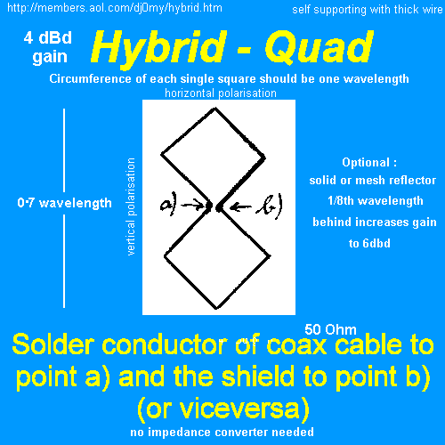
Hybrid Quad
4 dB gain over a dipole, if you fancy experimenting...